3:00_
3:15_
3:30_
3:45_
4:00_
4:15_
4:30_ Debbie Lin 500S
4:45_ Jessica 500N
5:00_
Saturday, February 28, 2009
Wednesday, February 25, 2009


Monday, February 23, 2009


Sunday, February 22, 2009


Saturday, February 21, 2009
fun with subD's!
So for this tutorial we will use a typical workflow that manipulates polygon geometry to produce a smooth subD object. Most of the polygon tools that we will use should be familiar by now.
Create a poly plane and give it 5 subDivisions in width and height (under Inputs in the Channel Box Editor). Rotate the plane 90 in the X direction.
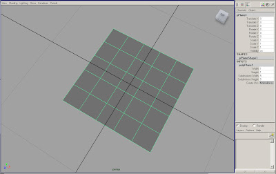
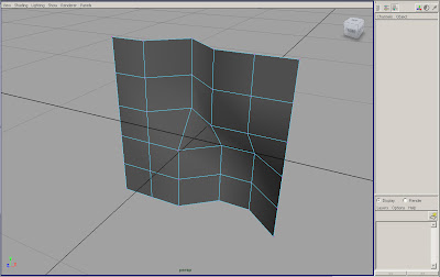
Go into Vertex mode and make some distortions to the plane. (hold rt mb and select vertex mode)
 We will use the EDIT MESH_BRIDGE, EDIT MESH_INSERT EDGE LOOP, EDIT MESH_ADD DIVISIONS commands several times. To make it easier for ourselves we can add these commands to the CUSTOM shelf. Make sure that you are in the polygon menus at the top left of the screen. Click on the Custom tab to bring the Custom shelf to the front. Holding Ctrl_Alt_Shift select EDIT MESH_Bridge. Notice that an icon will appear in the custom shelf. Repeat for the other commands.

Create a poly plane and give it 5 subDivisions in width and height (under Inputs in the Channel Box Editor). Rotate the plane 90 in the X direction.

Go into Vertex mode and make some distortions to the plane. (hold rt mb and select vertex mode)
 We will use the EDIT MESH_BRIDGE, EDIT MESH_INSERT EDGE LOOP, EDIT MESH_ADD DIVISIONS commands several times. To make it easier for ourselves we can add these commands to the CUSTOM shelf. Make sure that you are in the polygon menus at the top left of the screen. Click on the Custom tab to bring the Custom shelf to the front. Holding Ctrl_Alt_Shift select EDIT MESH_Bridge. Notice that an icon will appear in the custom shelf. Repeat for the other commands.
Add some edge loops to the surface. (it isn’t important that your geometry matches mine)
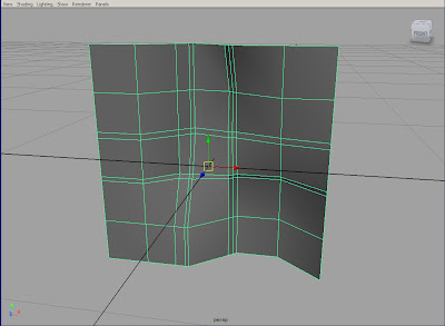
Create a ploy sphere and give it a radius of .1 and 4 subDivisions in Axis and Height. Make the geometries one with MESH_COMBINE, then delete its history since we won’t be going back to either objects input parameters. EDIT_DELETE BY TYPE_HISTORY.
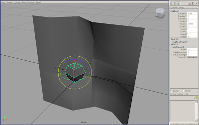
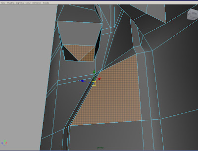
Select a face on the plane that we will link to the sphere. Click on the ADD DIVISIONS icon in you custom shelf.

Select a face on the plane and a face on the sphere to delete.

Delete two more faces and Bring up the Bridge menu by clicking the box next to EDIT MESH_BRIDGE. Select Smooth Path + Curve and click on Bridge.


Create a ploy sphere and give it a radius of .1 and 4 subDivisions in Axis and Height. Make the geometries one with MESH_COMBINE, then delete its history since we won’t be going back to either objects input parameters. EDIT_DELETE BY TYPE_HISTORY.

Select a face on the plane that we will link to the sphere. Click on the ADD DIVISIONS icon in you custom shelf.

Select a face on the plane and a face on the sphere to delete.
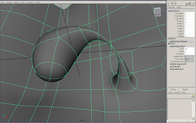
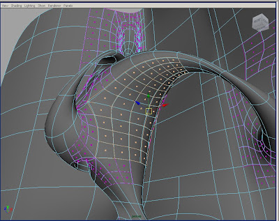
Add another command to the custom shelf. Hold Ctrl_Alt_Shift and go to SELECT_BORDER EDGE TOOL. Use the border edge select to select the edges around the two holes we created (holding shift). Click on the Bridge tool. In the channel box editor under the polyBridgeEdge1 inputs, select BEND for CurveType. Click on the other options like twist so that it is highlighted with a black bar and mmb (middle mouse button) click and drag in the viewport to dynamically change the value. I ended up using -60 for twist, 0 for taper, and 5 for divisions. Hit 3 to go into subD approximation and play around with the values.

Delete two more faces and Bring up the Bridge menu by clicking the box next to EDIT MESH_BRIDGE. Select Smooth Path + Curve and click on Bridge.

In the Outliner under polySurface1 you can select the curve that drives the bridge we just made. If you go to the surfaces menu at the top left of the screen we can rebuild the curve by selecting the menu box next to EDIT CURVES_REBUILD CURVES, put 6 for the number of spans.
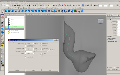
Move your view until the curve isn’t hidden behind the plane, press and hold rt mb over the curve and select control vertex mode. Now we can manipulate the path of the bridge by moving the points on the curve.
With the object selected bring up the Attribute editor (ctrl a). Click on the polyBridgeEdge2 tab, increase the taper amount, and change the path under Taper Curve by dragging the little circle around and adding new curve points by clicking on the black line.
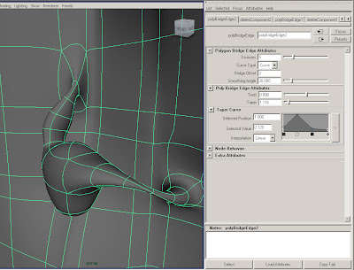
Let’s do one more bridge. Select two of the triangular faces on the bottom of the sphere and one face on the surface to delete. It is important that the holes or border edges have the same number of verticies in order to bridge, otherwise you can use the append polygon tool.
After getting your divisions, taper and twist amounts how you like them we can select and move some of the edge loops to shape the geometry. SELECT_EDGE LOOP to grab a continuous loop, move, rotate or scale the loop.
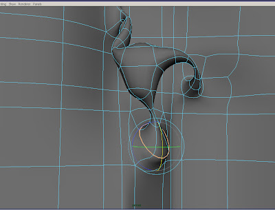
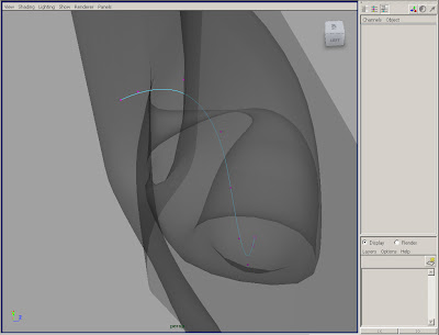
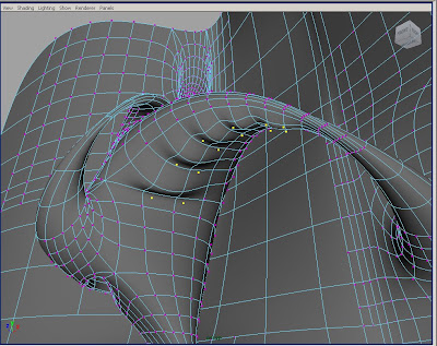
Select two triangular faces from the top of the sphere and one face on its side, delete. Again make a bridge, using the Smooth Path + Curve in the Bridge menu. Move the points on the curve creating another arm attaching to itself.


Move your view until the curve isn’t hidden behind the plane, press and hold rt mb over the curve and select control vertex mode. Now we can manipulate the path of the bridge by moving the points on the curve.

With the object selected bring up the Attribute editor (ctrl a). Click on the polyBridgeEdge2 tab, increase the taper amount, and change the path under Taper Curve by dragging the little circle around and adding new curve points by clicking on the black line.

Let’s do one more bridge. Select two of the triangular faces on the bottom of the sphere and one face on the surface to delete. It is important that the holes or border edges have the same number of verticies in order to bridge, otherwise you can use the append polygon tool.

After getting your divisions, taper and twist amounts how you like them we can select and move some of the edge loops to shape the geometry. SELECT_EDGE LOOP to grab a continuous loop, move, rotate or scale the loop.

Select two triangular faces from the top of the sphere and one face on its side, delete. Again make a bridge, using the Smooth Path + Curve in the Bridge menu. Move the points on the curve creating another arm attaching to itself.

Select one triangular face on the bottom and a face on the side. Delete and Bridge using a linear Curve Type in the channel box editor. This will create a hole through the sphere. Give it 6 or 7 divisions.
Next we will convert the poly object to a subD. Bring up the Convert Polygons to Subdiv Option menu MODIFY_CONVERT_ POLYGON TO SUBDIV. Add some extra zeros to the Maximum base mesh faces. And Hit apply. Toggle the 1,2 and 3 keys.


Next we will convert the poly object to a subD. Bring up the Convert Polygons to Subdiv Option menu MODIFY_CONVERT_ POLYGON TO SUBDIV. Add some extra zeros to the Maximum base mesh faces. And Hit apply. Toggle the 1,2 and 3 keys.

To convert the geometry back without changing the original Bring up the CONVERT_SUBDIV TO POLY menu. For Tessellation Method use vertices with Level 0. 

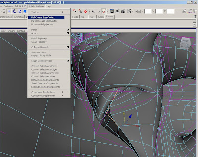
Now that we are working with subdivision geometry we can make some modifications with subdiv tools. Select some edges like below and try creasing them. Make sure your in the surfaces menu, and go to SUBDIV SURFACES_FULL CREASE.
Select another edge and try the partial crease, twice by hitting g for the second partial crease.

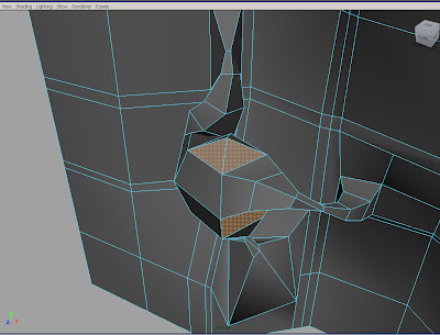
Go into face mode, select a couple of faces, rt click and select Refine Selected. This will increase the geometry locally so we can make detailed changes.
Select a number of separate faces in the refined area. Go to Subdiv Surfaces and try converting the selection to verticies, or edges. SUBDIV SURFACES_CONVERT SELECTION TO VERTICES. When you have some geometry selected make some changes like below.
Then before you deselect the vertices, convert the selection to edges. Deselect the edges you don’t want and make a full crease. If you undo some changes you’ll notice that the object retains the extra geometry. To clean this up go to SUBDIV SURFACE_CLEAN TOPOLOGY.

If you want to make some more changes in that same area, then go into vertex mode and by right clicking select the highest display level available (mine was 5). If you want to make more global changes, go to a lower level of display like 0 or 1 and make some changes by moving the faces.


Select another edge and try the partial crease, twice by hitting g for the second partial crease.

Go into face mode, select a couple of faces, rt click and select Refine Selected. This will increase the geometry locally so we can make detailed changes.

Select a number of separate faces in the refined area. Go to Subdiv Surfaces and try converting the selection to verticies, or edges. SUBDIV SURFACES_CONVERT SELECTION TO VERTICES. When you have some geometry selected make some changes like below.

Then before you deselect the vertices, convert the selection to edges. Deselect the edges you don’t want and make a full crease. If you undo some changes you’ll notice that the object retains the extra geometry. To clean this up go to SUBDIV SURFACE_CLEAN TOPOLOGY.

If you want to make some more changes in that same area, then go into vertex mode and by right clicking select the highest display level available (mine was 5). If you want to make more global changes, go to a lower level of display like 0 or 1 and make some changes by moving the faces.

That’s it!!! Now you’re a subD expert.


Friday, February 20, 2009
Assignment 1

The diagonals were created by intersecting another torus with a plane at 45 degrees, duplicating the curve and then using the duplicate special.
Monday, February 16, 2009
Final Project : model an architecture of your own creation

Using NURBS, Polygon and/or Sud-Division Surface geometry, model an architecture of your own creation. This can be any style, any scale, in part or whole.
Students may work individually or in small groups (pairs is suggested) students will first present concept imagery (photos, sketches, drawings, etc.) and then execute 3D computer model inspired by those images. In addition to realizing the look and feel of the concept imagery, students should pay particular attention to which geometries types and workflows they choose to acheive their desired results.
Preliminary Requirements: (via Blog, due feb 23, 2009 @ 5pm)
1. Concept Sketches/Imagery (jpegs or pdfs)
Final Requirements: (via CD)
2. 30 Second Video showing both wireframe and solid views.
-File format: .mov (quicktime), mpeg4 compression
-Resolution: 720 x 480, square pixels
-Credits must include:
-Your names
-My Name (Chris Whitelaw)
-This course (A4744: Geometries & Envelopes)
3. Maya Files
Sunday, February 15, 2009
Tutorial 2_spider joint_ continued
Now that the bolt is finished we can begin the geometry for the base and arms. First to align our images select the top camera and in the Attribute editor under the ImagePlane1 tab_PlacementExtras_Center put in -4.25 for the z value. Your images should be aligned like below. If you cannot see the images in perspective then for each camera go to the imagePlane tab and under the ImagePlaneAttributes_Display make sure “in all views” is checked.

Next create a polygon cylinder and rotate by 90 in the X direction. Radius 3 and Height 2.2. Move into place so it aligns im both views.
MESH_OFFSET EDGE LOOP on the top and bottom of the cylinder.

Select the faces in the center on the top of the base. Extrude the faces in to align with the inner circle. Press g and extrude again to make the pocket.

Insert an edge loop at the top and bottom of the pocket like below. Toggle between 1 and 3 to see how it looks in subD approximation mode.

Select the three faces on the side of the base that the arm will project from. EDIT MESHS_ADD DIVISIONS. In the Channel Box under Inputs make the divisions 1.

Select the faces that the arm will project from and delete.

To make the piece at the end of the arm create another polygon Cylinder give it a radius of 2, height .6, rotate X 90. Position so it aligns in both view.

Offset edge loops both at the top and bottom of the cylinder, and insert an additional loop on the side and on the top, like below.

Offset edge loops both at the top and bottom of the cylinder, and insert an additional loop on the side and on the top, like below.

Select the SoftMod tool. This will put a handel on the verticies that we selected allowing us to make changes with a gradient effect on our geometry. To change the center of the gizmo click the little circle outside and at the bottom of the softMod gizmo.

Snap (holding v) the gizmo to the vertex at the top of the disk and aligned with the center of the arm like below, and then click on the little blue circle again to get out of the gizmo mode.

In the top view move the softMod up until it aligns with the top of the lip.

Next change the Falloff Radius in the channel box editor under outputs until it aligns with the image. I used 3.2.

Select the inner loop on top of the disk and use the EDIT MESH_CREASE TOOL to harden the edge. Use a value of 2.
Next select the faces and edges like in the image below and use the EDIT MESH_WEDGE TOOL . Use a wedge angle of -30, and divisions 1.

With the faces still selected, scale them 1D by dragging the green box in until the surface appears flat. Also insert a new edge loop on the inside and near the bottom of the lip.

Delete the faces where the arm will attach.

Select both the base and the disk and make them one object MESH_COMBINE. Use SELECT_BORDER EDGE TOOL and select the edges on both of the openings we created. Make the geometry of the arm by using EDIT MESH_BRIDGE.

Go into face mode and delete all the faces of the base so that we are left with only ¼ of the spider joint.
To finish bring up the menu for MESH_MIRROR GEOMETRY. It seems to work better when you uncheck Merge with original. Mirror in the –X, and then in +Y. After select all of your verticies and EDIT MESH_MERGE to make the geometry clean.

Subscribe to:
Posts (Atom)